Heat Pump Buffer Tanks vs Volumiser Tanks Explained
Learn how buffer tanks and volumisers affect heat pump efficiency, compressor lifespan, and room temperature stability in UK home heating retrofits.
- Written by
- Net Zero Home Scheme editorial team
- Last updated
- Topic
- heat pumps, energy efficiency, mcs
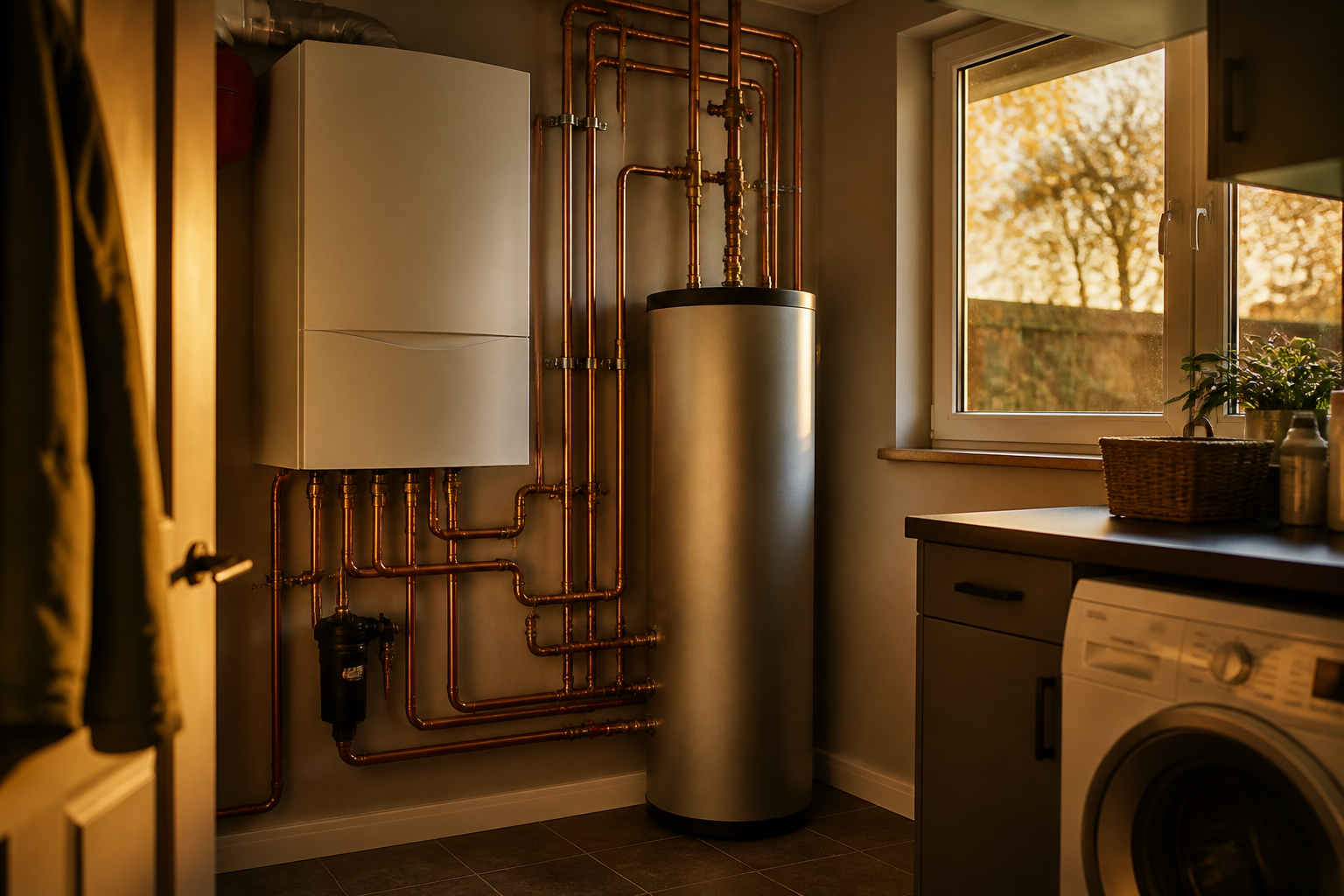
When replacing a gas boiler with an air source heat pump, system designers must ensure the heating circuit contains enough water to operate smoothly. Unlike gas boilers, which can rapidly ramp burner output up and down across a wide temperature range, air source heat pumps rely on steady water flow rates and precise system volumes to maintain efficiency. Two primary hydraulic components are used to address water volume limitations: volumiser vessels and 4-pipe buffer tanks.
Choosing between these two options is one of the most critical decisions in heat pump design. A wrongly specified hydraulic arrangement can reduce your system Seasonal Coefficient of Performance (SCOP) by 10% to 15%, increasing annual running costs. This guide explains the underlying physics, system hydraulics, and practical trade-offs involved in specifying volumisers versus buffer tanks.
Why heat pumps need minimum system water volume
Air source heat pumps require a minimum volume of circulating water within the active heating circuit, typically between 10 and 20 litres per kilowatt of compressor thermal output, according to installation standards such as MCS MIS 3005-D. Water volume serves two essential physical functions: preventing compressor short-cycling and providing energy for ice defrosting.
First, compressor short-cycling occurs when the heat pump generates more thermal energy than the emitters (radiators or underfloor heating) can dissipate at a given moment. If total system water volume is too small, flow and return temperatures rise rapidly, forcing the compressor to shut down. Once the small volume of water cools off a few minutes later, the compressor restarts. Repeated start-stop cycles increase mechanical wear on the inverter compressor and drastically lower seasonal efficiency.
Second, heat pumps operating in cold UK winter conditions (typically below 5°C outdoor ambient temperature) collect frost on their external evaporator coils. To clear this frost, the unit enters a defrost cycle, reversing its refrigeration cycle to extract heat from the indoor water circuit and dump it into the outdoor coil. If the active circuit lacks sufficient water volume, flow temperatures inside the home drop sharply during defrosting, causing noticeable cooling in radiators and potential low-flow fault codes.
How a volumiser works
A volumiser (often called an inline volume vessel or 2-pipe vessel) is a simple insulated container added directly in series with the main flow or return pipe of the heating circuit. It acts purely as a neutral thermal storage reservoir, adding 20 to 50 litres of water to the total circuit volume without separating hydraulic flows.
Because the volumiser sits in series within a single loop, water passes directly from the heat pump to the emitters without hydraulic separation. The main circulating pump inside the heat pump unit pushes water through both the volumiser and the radiators simultaneously.
The primary benefit of an inline volumiser is that it introduces zero temperature penalty. The flow temperature leaving the heat pump matches the flow temperature entering the radiators. Preserving this temperature alignment keeps the flow temperature as low as possible, directly maximising the heat pump COP.
However, a volumiser requires an open, unrestricted hydraulic path. If thermostatic radiator valves (TRVs) on most radiators close down simultaneously, the active circulating volume drops, restricting flow through the heat pump and risking high-pressure trip faults.
How a 4-pipe buffer tank works
A 4-pipe buffer tank acts as a hydraulic separator. It creates two completely independent circulating loops: a primary loop between the heat pump and the buffer tank, and a secondary loop between the buffer tank and the home heating emitters, powered by a separate secondary circulating pump.
Hydraulic separation decouples the flow rate of the heat pump from the flow rate of the radiators. If TRVs close across multiple zones in the house, reducing secondary flow, the heat pump continues to circulate water through the primary side of the buffer tank at its required flow rate without faulting.
While this provides hydraulic flexibility, 4-pipe buffer tanks introduce a physical phenomenon known as thermal mixing loss. Inside the buffer tank, cooler return water from the heating circuit mixes with hot flow water from the heat pump. As a result, the flow temperature sent to the radiators is typically 2°C to 5°C lower than the temperature generated by the heat pump compressor.
According to thermodynamic principles codified by the Energy Saving Trust and Heat Pump Federation, every 1°C increase in required flow temperature reduces heat pump compressor efficiency by approximately 2.5%. Generating 45°C water at the heat pump to deliver 42°C water to radiators incurs a permanent energy penalty on your running costs.
Comparing buffer tanks and volumisers
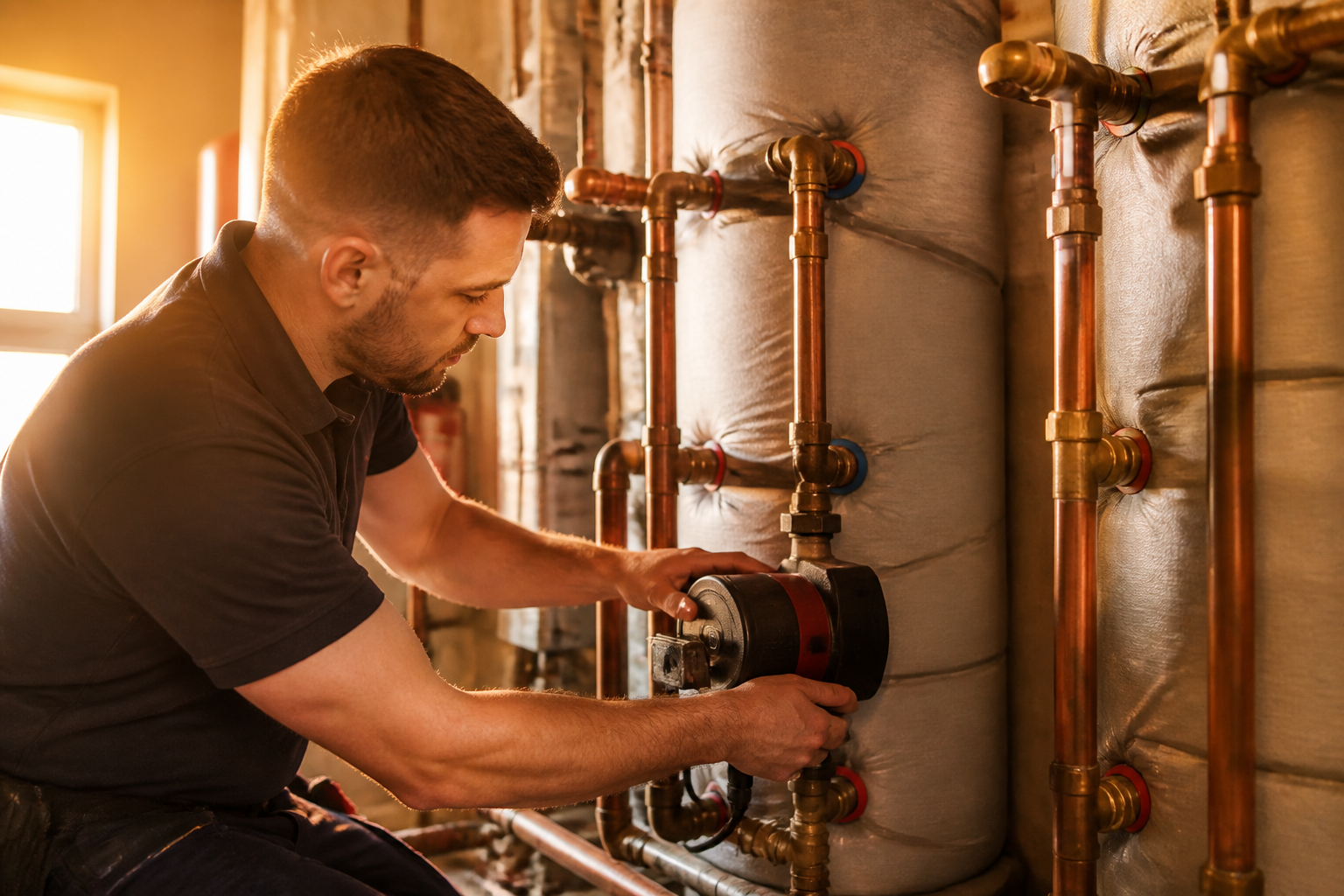
The following table outlines the key operational differences, efficiency impacts, and physical trade-offs between an inline volumiser and a 4-pipe buffer tank.
| Feature | Inline Volumiser (2-Pipe) | Buffer Tank (4-Pipe) |
|---|---|---|
| Hydraulic Setup | Series connection in single loop | Decoupled primary and secondary loops |
| Secondary Pump Needed | No (uses heat pump internal pump) | Yes (requires dedicated secondary pump) |
| Temperature Mixing Loss | None (0°C flow loss) | Yes (typically 2°C to 5°C drop) |
| System SCOP Impact | Preserves maximum SCOP | Reduces SCOP by 5% to 12% |
| TRV Zoning Flexibility | Low (requires bypass or open radiators) | High (supports independent micro-zoning) |
| Space Requirement | Compact (20L to 50L) | Larger (50L to 200L) |
| Installed Equipment Cost | Lower | Higher (requires extra pump and valves) |
Designing for maximum SCOP
To achieve the highest efficiency, modern UK heat pump design principles favour open-loop or volume-managed systems using inline volumisers rather than 4-pipe buffer tanks wherever practical.
An open-loop layout ensures that major heating zones (such as downstairs living areas) remain uncontrolled by TRVs, leaving radiators permanently open to act as a natural thermal store. If the open volume of the permanently connected radiators and pipework exceeds the manufacturer minimum specification (for example, 15 litres per kW), no additional vessel is needed. If the system volume falls short, a small inline volumiser provides the missing litres without compromising flow temperatures.
A 4-pipe buffer tank should generally be reserved for complex retrofits where secondary hydraulic flow cannot be guaranteed. Examples include large properties with multiple distinct heating zones, existing small-bore pipework that restricts flow rates, or hybrid configurations mixing high-resistance underfloor manifolds with radiator circuits.
What this means for you
When reviewing heat pump design proposals from installer engineers, pay close attention to how system water volume and hydraulic flow are managed:
- Ask your installer whether their design uses an open-loop layout with an inline volumiser or a 4-pipe decoupled buffer tank.
- Verify that your radiators are sized appropriately to keep flow temperatures as low as possible, ideally 45°C or lower on a peak winter design day (-3°C external).
- Avoid over-zoning with TRVs in every room if an open-loop strategy can maintain comfortable ambient temperatures using weather compensation controls.
- Check that all equipment installations comply with MCS MIS 3005-D standard specifications.
If your employer participates in the Net Zero Home Scheme, delivered by Net Zero Benefits alongside The Electric Car Scheme, you can access member pricing on heat pump installations with accredited installers across England, Scotland, and Wales without payroll deduction or salary sacrifice.
Frequently asked questions
Do all air source heat pumps require a buffer tank?
No. Many straightforward UK domestic installations operate on an open-loop system with an inline volumiser or sufficient pipework volume, eliminating the need for a 4-pipe buffer tank. Buffer tanks are only necessary when secondary zone valves or narrow pipework restrict primary water flow rates.
How much does a buffer tank reduce heat pump efficiency?
Because a 4-pipe buffer tank causes mixing losses that drop flow temperatures by 2°C to 5°C, the compressor must work harder to deliver the target temperature to radiators. This typically reduces the system Seasonal Coefficient of Performance (SCOP) by between 5% and 12%, resulting in higher annual electricity consumption.
Where are volumisers and buffer tanks usually installed?
Volumisers are compact, holding 20 to 50 litres, and are often fitted inside an airing cupboard, under-stairs space, or adjacent to the hot water cylinder. 4-pipe buffer tanks are larger, usually holding 50 to 200 litres, requiring dedicated floor space in a utility room, garage, or plant room.
Sources
- MCS MIS 3005-D: Heat Pump Systems Standard, Microgeneration Certification Scheme
- Heat Pump Systems Design Guide, Energy Saving Trust
- Code of Practice CP1: Heating Design Standards, CIBSE